CNC machining is a versatile machining method that produces high-quality results. To get the most out of the capabilities of CNC machining, though, you need to design parts that play to the method’s strengths and fit within its capabilities. You can make sure you do that by following some basic best practices.
CNC Design Restrictions
Although CNC machining is very versatile, the nature of the process does involve some design restrictions. Being aware of these limitations before you begin designing a part can help the whole process go more smoothly. CNC design restrictions are mainly due to the mechanics of the process, tool geometry and tool access.
1. Tool Geometry
The majority of CNC cutting tools are cylindrically shaped and have a restricted cutting length. As these tools remove materials from the workpiece, they transfer their geometry to the part they are machining. The internal corners of a piece, for example, invariably have a radius. This is true even if you machine them with an extremely small cutting tool.
2. Tool Access
CNC machining tools have a limited range of access, which creates certain design limitations. You must apply cutting tools to workpieces directly from above, and you cannot machine features that you cannot access from this angle. Undercuts, however, are an exception to this rule. We will cover how to design undercuts in a later section of this post. Tool access is also a concern when working on features that have a large depth-to-width ratio.
Following certain design for CNC machining recommendations, such as aligning all of the features of your part to one of the six principal directions , can help prevent tool access from becoming a problem. This is not as restrictive as it might at first seem since five-axis CNC systems have excellent workpiece holding capacity. If you need to access the bottom of a deep pit in the workpiece, you’ll need to use a specialized tool with a long shaft. While doing so is feasible, it increases vibration and reduces the accuracy you can achieve. When designing parts for CNC machining, you should aim to make them machinable with a tool that has as long a diameter and as short a length as is feasible.
Design Best Practices by Part Features
The CNC machining world does not have a set of standards that are accepted and used across the industry. The tools used in CNC machining, and therefore its capabilities, are also always evolving. This uncertainty is a challenge when it comes to the design of CNC machining parts.
However, various best practices can help you when designing parts. Following the recommended values and keeping the limits of technical feasibility in mind can help you ensure that you create a high-quality design.
1. Cavities and Pockets
The recommended depth of any cavity in your design is four times its width because end mill tools have a limit to their cutting length. This limit typically three to four times the diameter of the tool. Lower depth-to-width ratios lead to increased vibration, tool deflection and chip evacuation.
If you need larger depths for design, you can use variable cavity depth to get around this problem. It is possible to have a 30:1 ratio for tool diameter to cavity depth if using a specialized tool.
2. Internal Edges
When designing inner edges, the recommended vertical corner radius is one-third of the cavity depth or greater. If you use the recommended corner radii, you will be able to use a diameter tool that follows the suggested cavity depth guidelines. Corner radii slightly higher than the recommended amount enables you to cut along a circular path, rather than a 90-degree angle, which creates a surface finish that is of a higher quality. If you instead need a 90-degree angle, it is recommended that you use a T-bone undercut rather than decreasing the corner radius.
The recommended floor radius is 0.5 millimeters, one millimeter or no radius, although any radius is technically feasible.
3. Thin Walls
The walls of your CNC-machined part should ideally be at least 0.8 millimeters thick for metals or 1.5 millimeters thick for plastics, although thicknesses of 0.5 millimeters for metals and one millimeter for plastics are technically feasible.
Thinner walls increase the vibrations that occur during machining and reduce the degree of accuracy you can achieve. Thinner plastic walls may also warp because of residual stress or soften because of temperatures increases.
4. Holes
Machinists use either drill bits or end mill tools to machine holes. When deciding on the diameters of the holes in your design, use standard drill bit sizes, which are measured in either metric or imperial units, as a guide. Any diameter above one millimeter is technically possible. If holes require tight tolerances, machinists use reamers and boring tools to finish. It’s recommended to use a standard diameter for holes smaller than about 20 millimeters that need a high accuracy.
The maximum suggested depth of any hole is four times the nominal diameter, and 40 times this number is feasible. A typical ratio is around 10 times the nominal diameter.
5. Threads
When designing CNC-machined parts, the recommended thread size is M6 or above, but the minimum you can use is M2. For cutting threads down to M6, machinists use CNC threading tools, which reduce tap breakage risk. Taps and dies can cut down to M2.
The recommended thread length is three times the nominal diameter, and the minimum is 1.5 times the nominal diameter. For all threads that are below M6, you will need to add at the bottom of the hole an unthreaded length equaling 1.5 times the nominal diameter. For threads larger than M6, you can thread the hole throughout its length.
6. Small Features
You can include some small features in your design, but there are some best practices to help make sure they turn out the way you want them to. The recommended minimum diameter of any hole in a design is 2.5 millimeters. The majority of machine shops should be able to accurately machine holes of this diameter with standard tools.
With specialty tools called micro-drills, machinists with the necessary expertise can cut holes down 0.5 millimeters.
CNC Machine Tolerance
The term tolerance in machining refers to the amount by which a dimension is allowed to vary. Put another way, it’s the difference between the minimum and maximum limits of a specification.
1. General Tolerances
Some companies use a general tolerance if a customer has not provided a drawing or specification sheet. These tolerances vary from company to company, and some do not use default tolerances. These machinists instead require their customer to provide them.
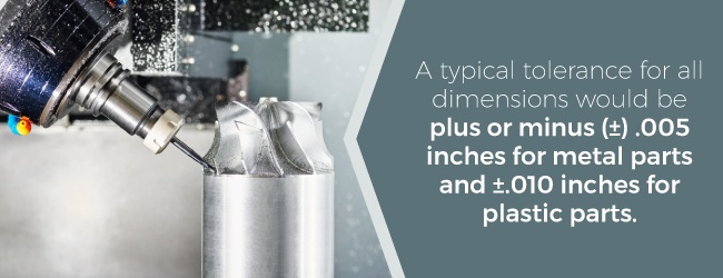
Companies that have general tolerances may have them for general dimensions, wall thickness, adding tapped holes and applying surface treatments. Although tolerances vary, an example of a typical tolerance for all dimensions would be plus or minus (±) .005 inches for metal parts and ±.010 inches for plastic parts.
2. Part Tolerances
You can request that a company use tolerances other than the general tolerances for your parts. You will determine what tolerance you wish to use based on each part’s fit, form and function.
Keep in mind that requesting tighter tolerances could increase your costs, as they could cause the project to take longer, increase scrap and require the use of more specialized measuring tools. To keep costs low, only apply tight tolerances to parts where it is critical to the design.
Size Limitations
The overall size of the part is, of course, an important consideration when designing it. The capabilities of the machines available to you, as well as the depth of cut required for your part’s feature, limit the size of your part. Keep these considerations in mind if your piece will be machined via milling or lathe.
1. Milling
When milling is used, the size of the part of its features will determine its machinable height. It’s important to remember that the dimensions of a build space are not the same as the feasible size of the parts it can machine. For instance, even though a machine may hae the ability to travel 38 inches along the Z axis, you can not machine a part to that depth or height. The part size and feature will need to be a little less than 30 inches to allow for tool clearance as well as the depth of cut.
2. Lathe
The largest possible size of a part you can machine with a lathe depends on the diameter and length of the build space. Companies with live tooling lathes can machine higher numbers of features while decreasing lead times. Live tooling lathes include extra CNC milling functions within the lathe.
Material
The materials that make up your part play a critical role in determining how well it functions as well as how much it costs. When choosing a material, you must balance optimal performance with cost.
To select the right material , identify the characteristics you need your chosen material to have. Hardness, weight, thermal stability, chemical resistance and heat treatability are all qualities you may need to consider. To determine the attributes you need, define the part’s functions, the environment it will function in, the stress load it must endure and any other relevant aspects of how the piece will be used.
You can use many different kinds of materials for CNC machining, but metals and plastics are the two most common types.
1. Metals
Manufacturers use various metals for CNC-machined parts, including steel, aluminum and brass. Softer metals like aluminum are easier to machine. Because working softer metals takes less time, using them is typically less expensive. The may also have lower weights. However, soft metals cannot take as much stress as harder metals, like stainless steel and carbon steel.
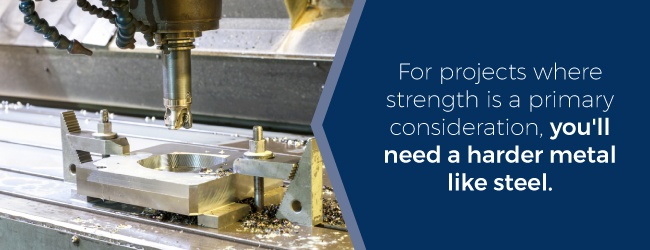
For projects where strength is a primary consideration, you’ll need a harder metal like steel. The downside to these materials is that they weigh more and take longer to machine, which can drive up the cost of the project.
The cost of the raw material, however, is also an important factor in determining the final price of a project.
2. Plastics
Plastics are a more cost-effective option as compared to metals, but they do not have the strength and rigidity that metals do. Plastics are typically easy to machine and cost much less as a raw material. Besides lack of strength, another drawback to using plastics is the fact that tight tolerances are sometimes harder to achieve. Parts are also more susceptible to warping under stress or high temperatures. However, if these are not concerns for your project, a plastic material could be an ideal option.
Complex Parts and Limitations
Tool access is a significant design limitation for CNC machining. Reaching multiple surfaces on a workpiece requires rotating it numerous times. Each time you turn a piece, you must recalibrate the machine and define a new coordinate system. Having to do this frequently can increase the amount of time it takes to complete a project and increase costs.
1. Five-Axis CNC Machining
Rotating a piece four or fewer times should not be a problem. If you need to rotate it more than that, the part is more complicated and would benefit from using five-axis CNC machining .
With five-axis CNC machining, you can follow more complex tool paths, which reduces machining times and results in a higher-quality surface finish.
Five-axis CNC machining still does have some of the same limitations as other methods. You still can not, for example, machine internal geometries. Using these more complex systems is also more expensive.
2. Designing Undercuts
Because standard cutting tools must access a piece from directly above, machining undercuts requires the use of specialized tools.
There are different design best practices for each of the two main kinds of undercuts — T-slot undercuts and dovetail undercuts.
T-slot cutting tools feature a horizontal cutting blade on a vertical shaft. The undercut’s width can be anywhere from three millimeters to 40 millimeters. It is recommended that you use whole increments or commonly used fractions when defining your undercut width.
Dovetail cutting tools vary based on their angle. The standard angles used are 45 and 60 degrees. You can also, however, find tools of five degrees and 10 degrees on up to 120 degrees in 10-degree increments. These are less common though.
If you are designing a part with an undercut on an internal wall, be sure you leave enough room for the tool. Typically, you will need at least four times the undercut’s depth in between the machined wall and other internal walls.
The standard ratio of cutting diameter and the shaft diameter is two to one, which limits the cutting depth. If you need a non-standard depth, however, machine shops can create custom tools, but this adds to lead time and project cost.
General Rules to Follow
Keep these rules of thumb in mind when completing your part design for CNC machining:
- Design your parts so that tools of the largest diameters possible can machine them.
- Add large fillets of at least a third the size of the cavity depth to interior vertical corners.
- Don’t design cavities that are more than four times deeper than their width.
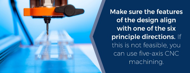
- Make sure the features of the design align with one of the six principal directions. If this is not feasible, you can use five-axis CNC machining.
- If your design includes specifications for things like tolerances, threads and surface finish, include a technical drawing with your design.
CNC Machining From American Micro Industries
Once you’ve designed the perfect part for CNC machining, you’re ready to find a partner to machine it for you.
American Micro Industries is the smart choice for your CNC machining project. We reliably produce high-quality parts and deliver them on time, even if you need a unique part that’s hard to find. We specialize in these custom solutions and will pay attention to every detail of your design. We can identify materials, produce parts and ship all from one location. Rest assured we will always stand behind our products and strive for complete customer satisfaction.
If you have questions, feel free to contact us, and if you have a design you need machined, you can request a quote here .

